How To Assemble John Deere Plug Aerator


I found the directions to be very good as usual. John Deere does a fantastic job with providing easy to follow assembly directions for all the their products that I’ve purchased so far. The following is a quick summary of the assembly process for a John Deere 40″ tow-behind plug aerator.


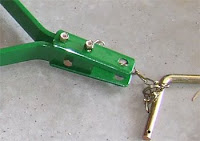
The first step is to connect the two tow bars to the tow hitch assembly. I’d say this was the only step that the directions weren’t as clear as they could be. If you look at the small photo of the hitch assembly it’s pretty straight forward. You connect the two tow bars together with one bolt while you “sandwich” those same two tow bars with the two “hitch” plates. The plates give you a place to install the hitch pin to connect the aerator to the mower.

The next step is to install the control arm. The control arm allows you to move the position of the plug spoons. There are three settings. One for
The final step is to assemble the wheels. This step is very straight forward as well. You install a bolt into each wheel then you bolt that to the frame.
I think the whole project would have taken me about 30 minutes if I wasn’t stopping every 5 minutes swapping wrenches with my son. Stay t
There are other Plug Aerator
Related Posts:
Should you buy John Deere Mowers at Box Stores?
John Deere Plug Aerator
John Deere Tow-Behind Broadcast Spreader
How To Change Oil, Air & Fuel Filters on John Deere X300
Recent Posts
Framing Stick Nailer vs Coil Nailer
Which is Better a Stick Nailer or Coil Nailer? Framers have many choices in nailers…
How Many Roofing Nails Per Square of Shingles
Estimating How Many Nails for a New Roof When it comes to estimating materials for…
Composite / PVC Decking – Layout Tips & Advice
Composite / PVC Decking Layout Tips and Advice Composite and PVC decking have really changed…
Benefits of an ERV System (Energy Recovery Ventilator)
Benefits of ERV Systems (Energy Recovery Ventilator) If you're building a new home or doing…
Vermiculite Attic Insulation Abatement
Vermiculite Attic Insulation If your home was built before 1990 there is a chance it…
Nuisance Tripping of AFCI (Arc Fault) Circuit Breakers
Arc Fault (AFCI) Circuit Breakers Tripping Often An arc-fault circuit interrupter (AFCI) or arc-fault detection…

View Comments
I noticed your plug aerator has more tines than the standard JD. Did you add more plugs?
It's the standard plug aerator, no modifications.
Really- and I'm not doubting you. I count 12 "tines". With 4 spoons each, that's 48 plugs.
With the setup I see here, I'd get a JD 40". According to the JD site, there are only 28 plugs. Hence my question.
Thanks and great site!
You're correct about the photo of on the JD site, they show fewer spoons. I just checked my order, it was the 40" model, so maybe they have changed the design...not sure.
The instructions have one major flaw. On page 25 under section "Install Tow Bars to Tray Assembly", they state "f. Stand plug tray assembly on its rear side.".
Unfortunately, the tray assembly looks symmetrical and thus to determine which side is the "rear" I looked to the picture "M78707" at that step. It shows the tray laying down with the "JOHN DEERE" logo face up. So I presumed that top face was the FRONT side. And in fact, on the very next page with photo M78700, they show just that (fully assembled). So that's the way that I assembled it.
Well guess what! That decal is NOT on the front side but is on the rear side. And so you go to the trouble (balancing act if you're handling this yourself) to install the tow bars only to find that when you get to installing the lift lever, the lever's on the wrong end!
Flip it over to the other side and re-install.
Here's a tip: Rather than standing on "end", flip it over (cardboard on floor so as not to mess up that beautiful paint job!) with the tines facing straight up, weight bucket face down on floor. Now it's a piece of cake for a single person to install bars.
BTW, I'd read about the error in assembly instructions somewhere else but I can't find it. So when I was installing, I kind of blew it off. A pity. That guy was right.
Just curious. Has anybody purchased a 48" aerator and received a tow bar assembly for a 40"?
There is no way the tow bar assembly with my aerator will work. Way too narrow.
Just bought the LPPA40JD aerator. Contrary to the assembly instructions, it is much easier for a single person IF you place the unit with the tines up. Then install each individual tow bar. Then install the hitch assembly. (Bring the ends of the tow bar together to about half an inch with the cross bolt.). Then install the two hitch plates. Was a breeze this way! Very happy with this purchase. BTW…. To determine the front of the unit for tow bar installation… with the unit tines facing up place the the control arm lever so the wheel bolt hole is pointing upward with the tines. The control arm now points to the rear of the unit. Happy aerating y’all!
Curious if you or anyone else has experienced, or heard of others who have experienced, an issue with the bending or deforming of the part that attaches the tire to the frame and the control arm to the point it pushes/angles the control arm away from the frame and therefore the hole (in the control arm) doesn't stay on the bolt holding it in position. The control arm isn't bent, it's the part the control arm (w/ the spring & nut) is connected to. It bent somehow, and now that side tire isn't perfectly straight and it won't stay "locked" in an any position...falls all the way down. Understand what I'm saying? Looks like I need to buy a replacement for that part. I hope that's it.